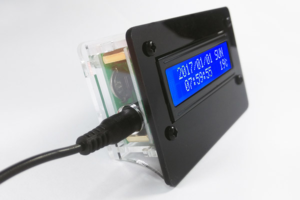
Installation Instructions for 1602 LCD Display Clock
This is a computer translation
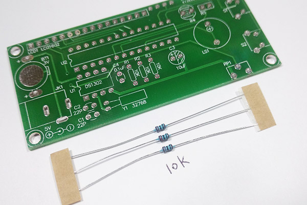
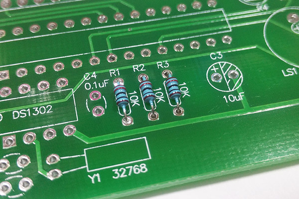
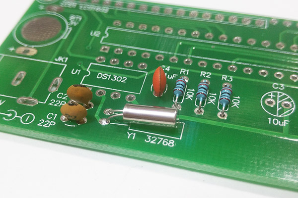
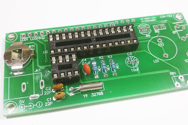
Install three 10K resistors, 10K resistor color ring is: brown black black red brown. The resistor has no positive and negative directions.
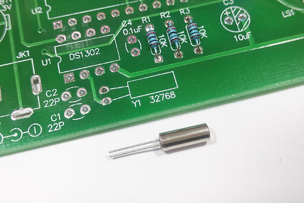
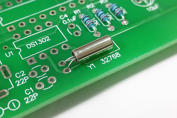
Install crystal, crystal no positive and negative direction, lying down installation. Note that the welding time is too long, the temperature can not be too high, crystal pin can not be too short.
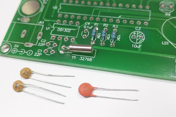
Install 22PF ceramic capacitors and 0.1UF (104) ceramic capacitors.
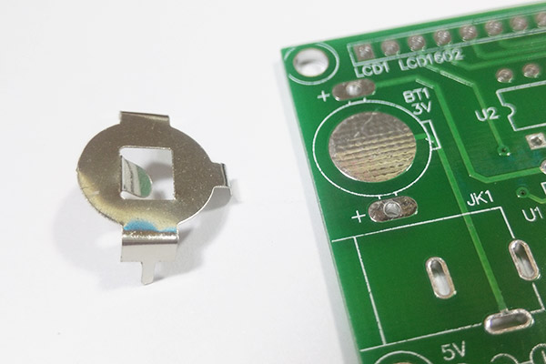
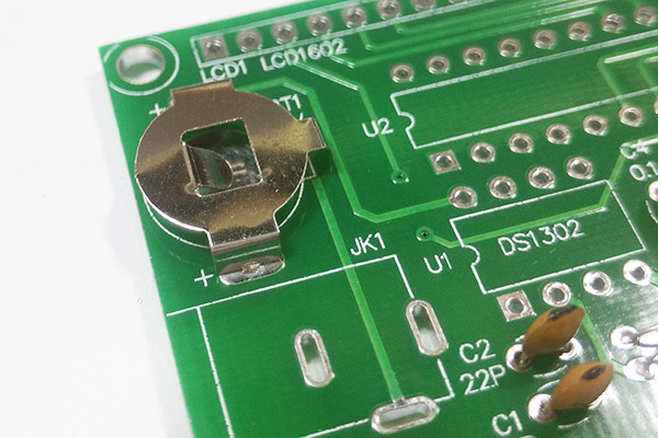
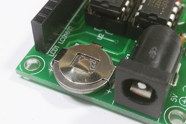
Install the battery holder and install the battery holder in the direction shown below.
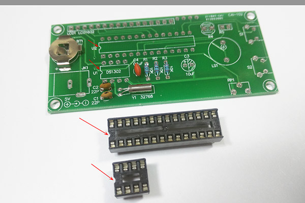
Installation IC block, IC block is mainly to facilitate the integrated circuit can be removed, IC seat gap direction against the circuit board with a notched mark on the location.
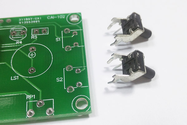
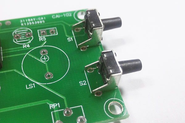
Install the touch switch.
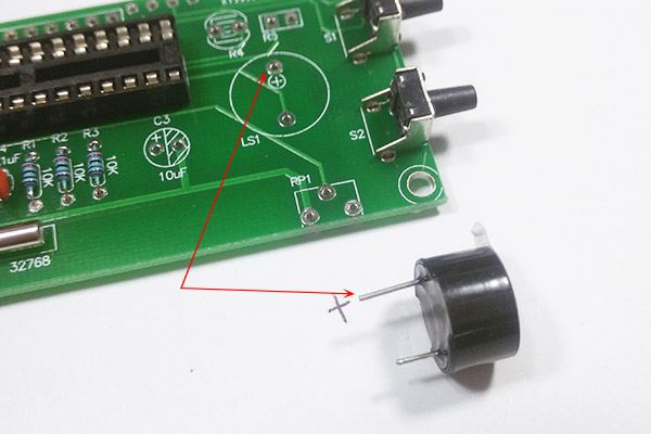
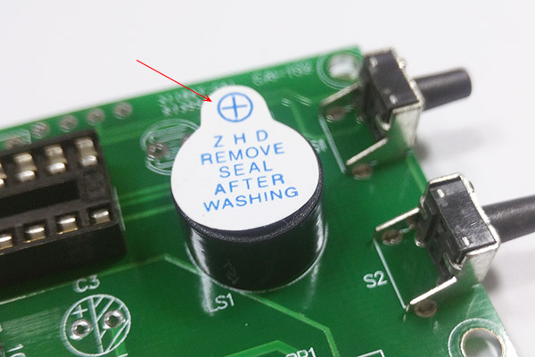
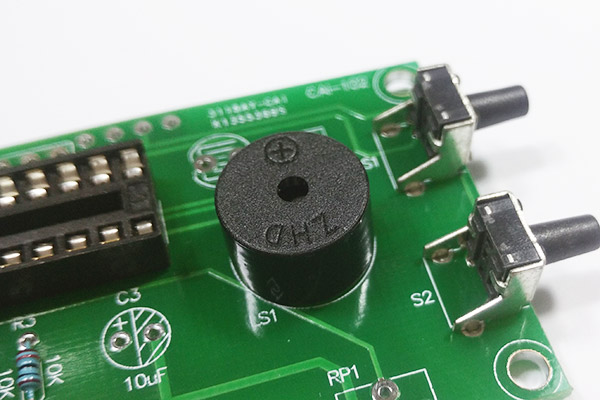
Install the buzzer, buzzer long foot is positive, facing the circuit board with a positive position, installed after the stickers tear up, easy to speak out,
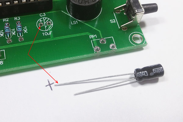
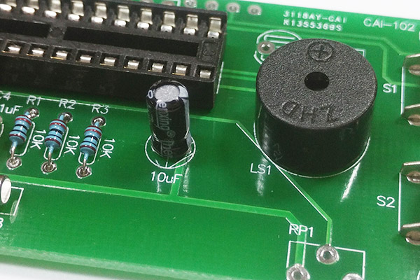
Install 10uf electrolytic capacitor, electrolytic capacitor long legs are positive, facing the circuit board with a positive position.
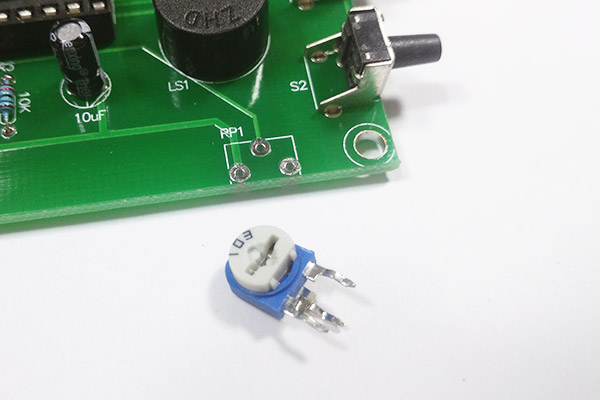
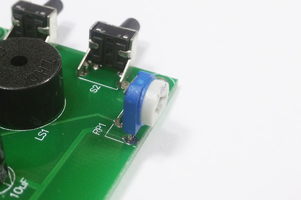
Install 103 blue and white potentiometer. This potentiometer is to adjust the contrast, installed after the power, adjust the potentiometer to let the figures show.
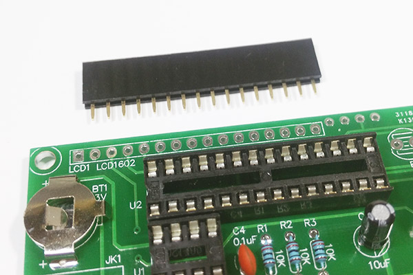
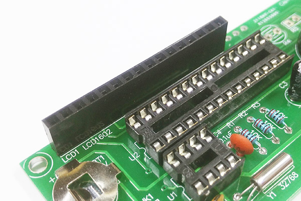
Install 16-pin IC locator.
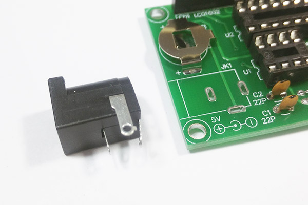
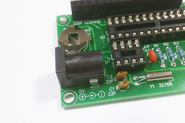
Install the power supply terminal.
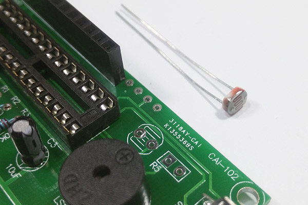
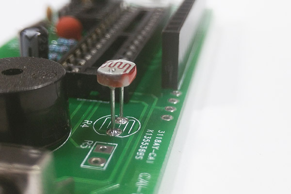
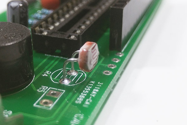
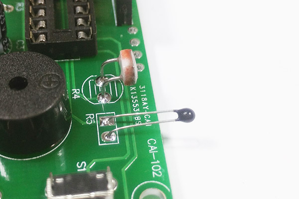
Install the photoresistor, the photoresistor has no positive and negative direction. Photosensitive resistance from the circuit board 1CM or so, pay special attention to the welding temperature can not be too high, easy to damage the photosensitive resistor, welding will be good after the bending resistance of 90 degrees, as shown below.
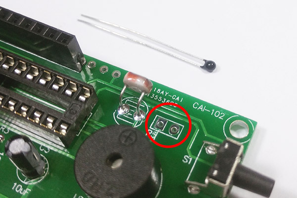
Install thermistor, thermistor, no positive and negative direction. Thermistor left about 2cm length, easy to detect the shell to measure the ambient temperature.
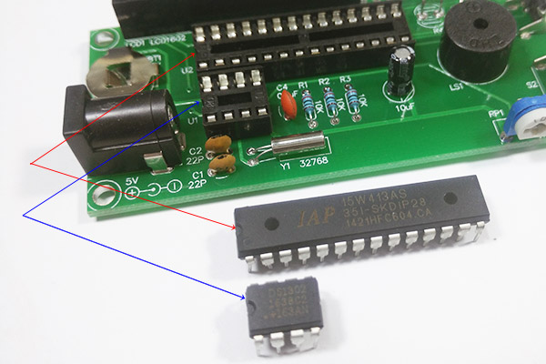
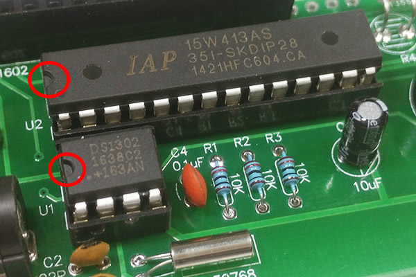
Installation of integrated circuits (ICs), large integrated circuit model is IAP15W413AS, small is DS1302, integrated circuit power supply can not exceed 5.5V, more than 5.5V power supply will burn out. The same is the direction of the gap when facing the circuit board with a gap mark on the location.
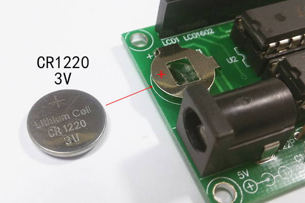
Install the button battery, button battery is starting from the memory time, that is, although the clock is not shown after the power, but the time or continue to walk.
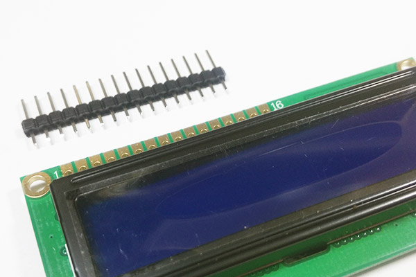
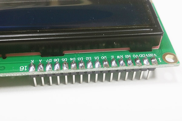
Install the LCD pin
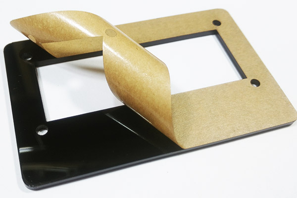
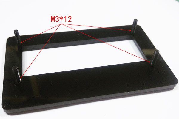
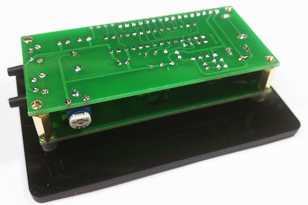
Install the shell, first tear off the protective film of acrylic.
Fitted with 4 black screws.
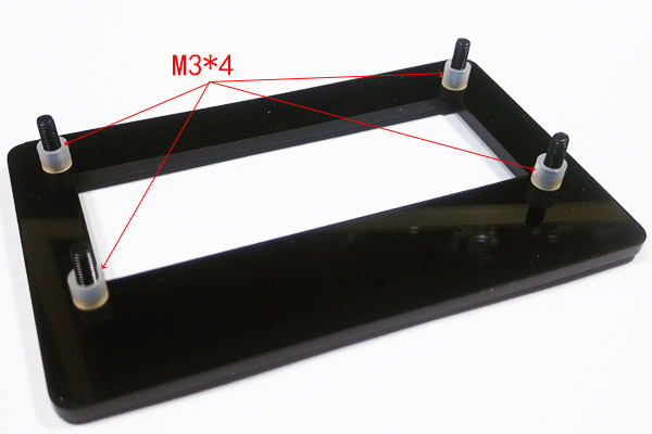
Fitted with 4 spacers
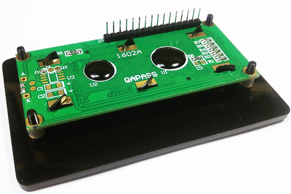
Fitted with LCD screen
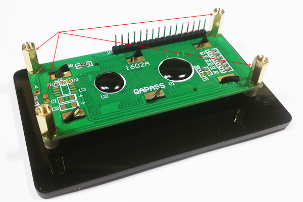
Fix the LCD screen with 4 pillars
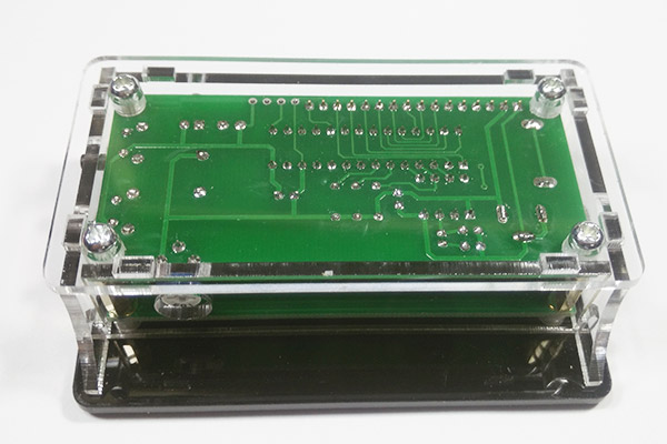
Install the circuit board and insert the pinhole of the circuit board
Install the 4-week strip and tear the protective film at the same time.
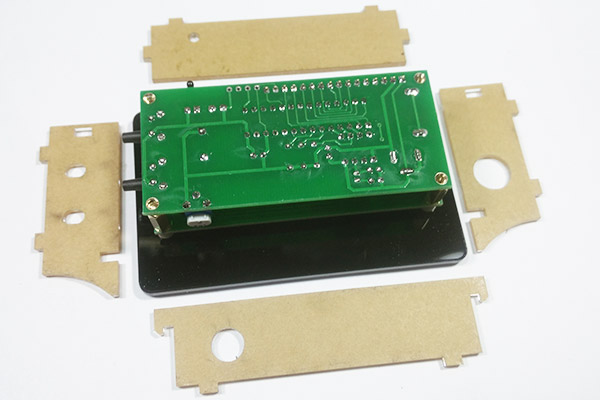
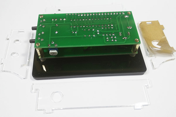
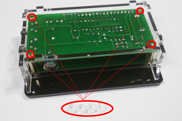
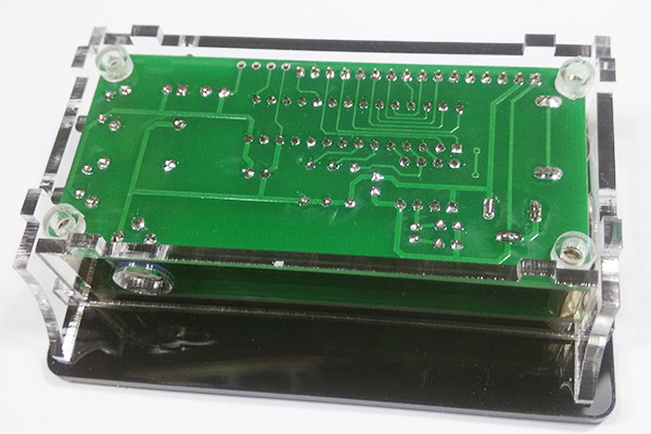
Place 4 transparent gaskets in 4 corners. For fixed circuit boards.
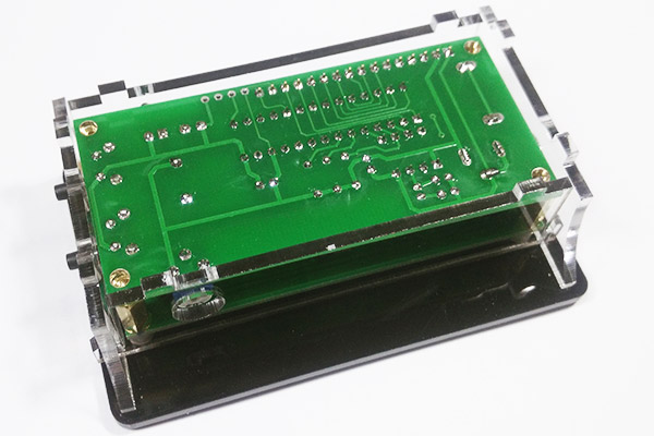
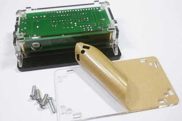
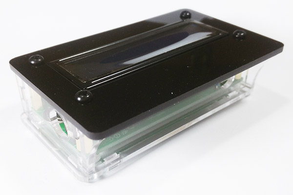
Remove the protective film from the rear panel and install it with a screw.
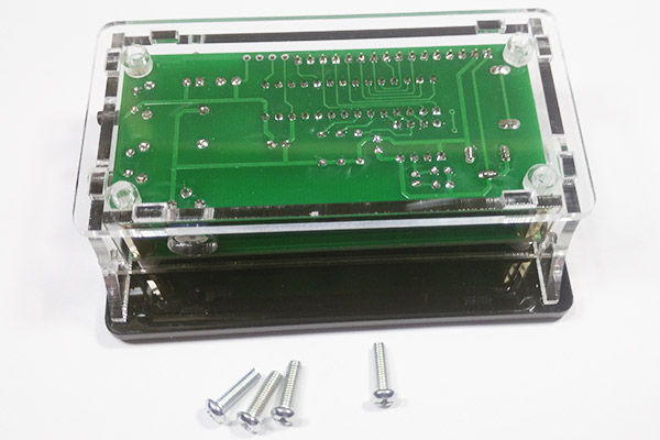
Installed shell.
To the same circuit on the 5V power supply, in accordance with the instructions to adjust.