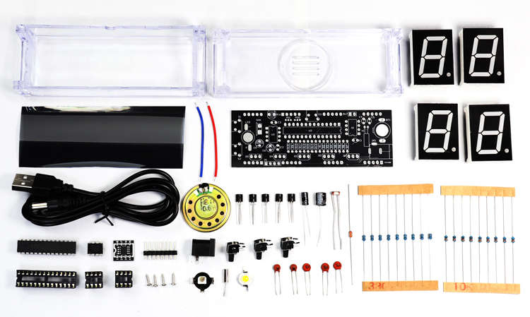
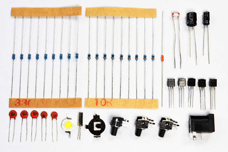
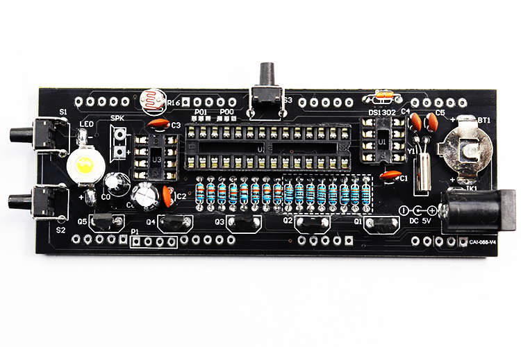
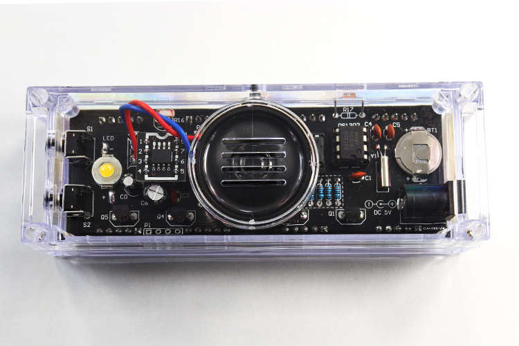
↓配件图
Component photo
↓安装330Ω电阻器,无正负极。
Install 330Ω resistor without positive and negative poles.

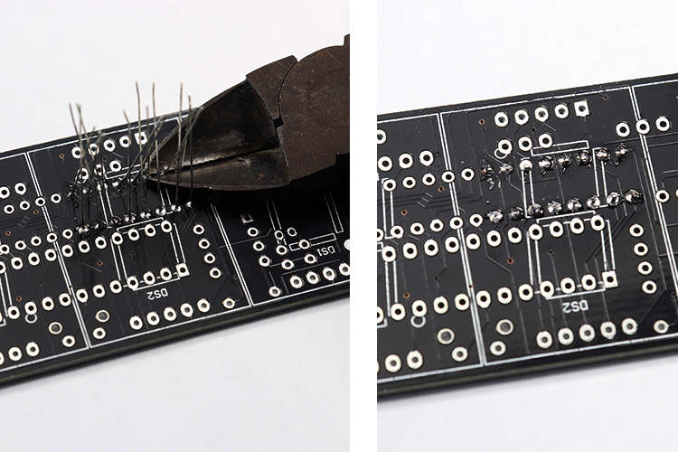
↓将元件引脚剪去,再焊接下一部分。
Cut the component pins and solder the next part.
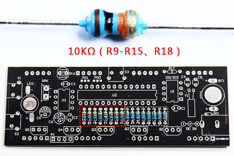
↓安装10KΩ电阻器,无正负极。
Install 10KΩ resistor without positive and negative poles.
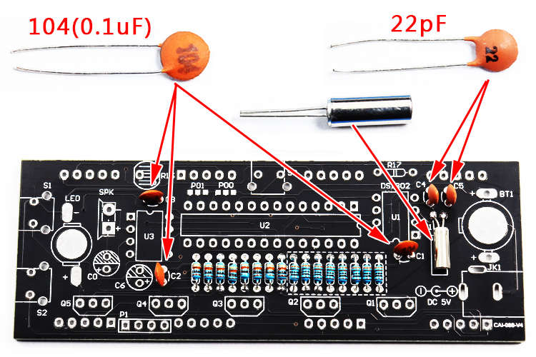
↓安装晶振,104瓷片电容和22pF瓷片电容,没有正负极。
Install crystal, 104 ceramic capacitors and 22pF ceramic capacitors, no positive and negative.
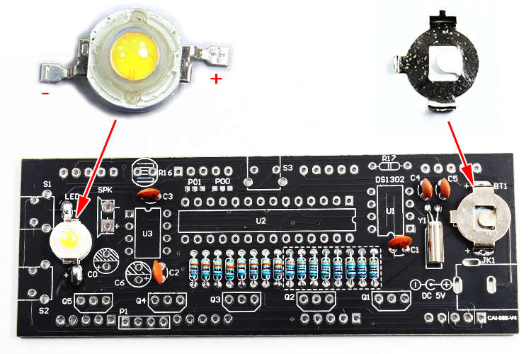
↓安装1220电池扣和LED灯,LED注意区分正负极。
Install the 1220 battery holder and LED lights. The LED should be distinguished from positive and negative.
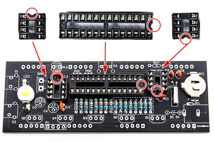
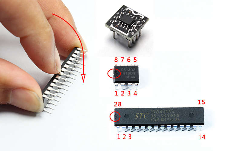
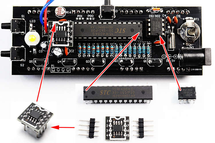
↓安装IC座,注意缺口位置对应电路板带标记的位置。
Install the IC holder. Note that the position of the notch corresponds to the marked position on the circuit board.
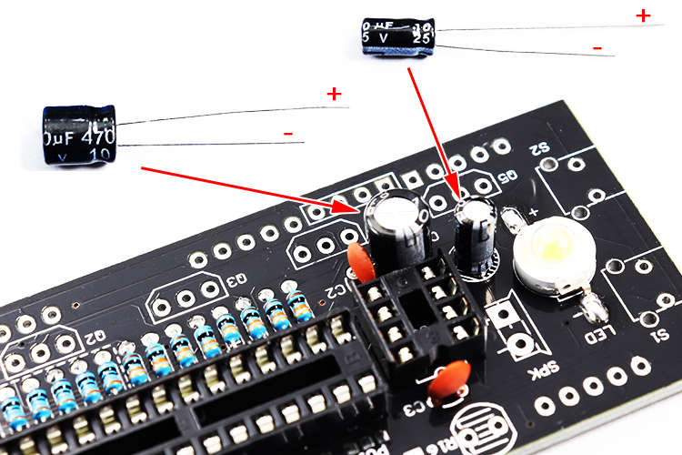
↓安装电解电容器,注意,长脚是正极。
Install the electrolytic capacitor. Note that the long leg is positive.
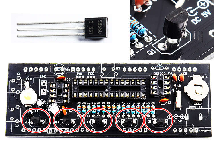
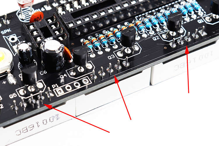
↓安装三极管,如图所示的方向安装。
Install the triode, and install it in the direction shown in the figure.
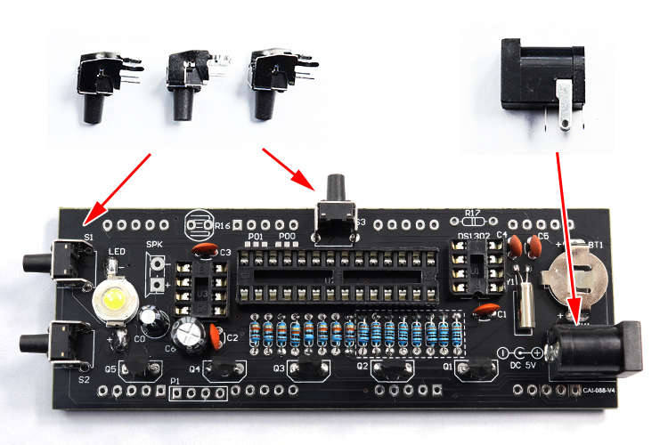
↓安装轻触开关和电源座,如图所示安装。
Install the tact switch and the power socket, and install as shown.
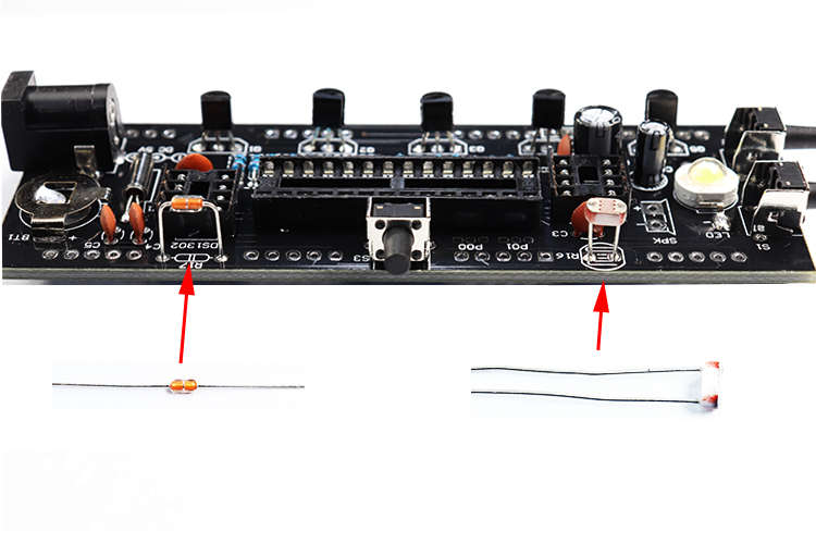
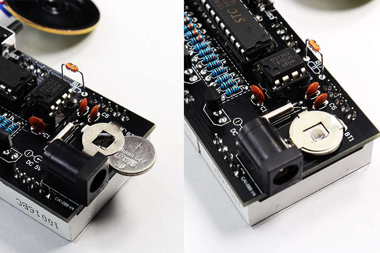
↓安装光敏电阻和热敏电阻,无正负极,如图所示安装。
Install the photoresistor and thermistor without positive and negative poles. Install as shown.
↓检查元件是否安装错误。
Check whether the component is installed incorrectly.
↓检查焊点是否良好,是否有短路,是否漏焊。
Check whether the solder joints are good, whether there is a short circuit, and whether there is leakage.
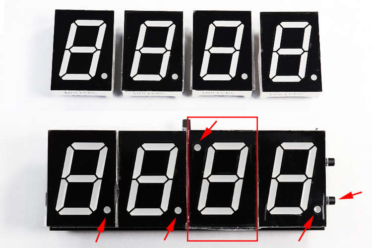
↓安装数码管,第3位数码管要倒立安装。如图所示。
Install the digital tube, the third digital tube should be installed upside down. as the picture shows.
↓将数码管焊接好
Weld the digital tube
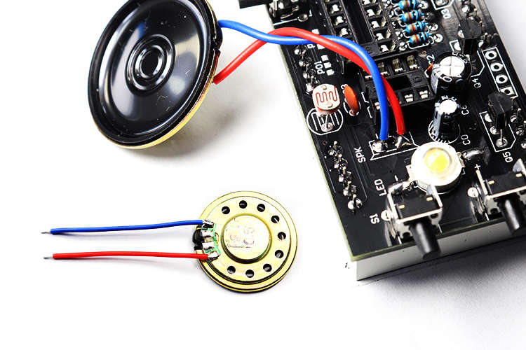
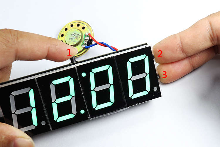
↓安装喇叭,不用区分线的颜色和正负极。
Install the speaker without distinguishing the color of the wire from the positive and negative poles.
↓将集成电路的引脚校正
Straighten the pins of the IC.
↓将集成电路装入IC座,如图所示。
Install the IC into the IC holder as shown in the figure.
↓将电池装入。
Insert the battery.
↓通电5V,对电路复位,同时按住三个按键5秒以上。复位后显示12.00
Power on 5V to reset the circuit. Press and hold the three buttons simultaneously for more than 5 seconds. Display 12.00 after reset
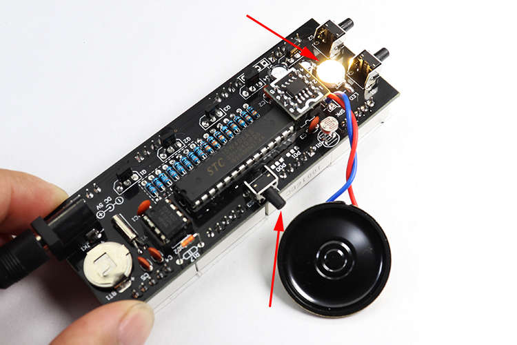
↓长按顶部开关,打开LED。再次长按顶部开关,关闭LED。
Press and hold the top switch to turn on the LED. Press and hold the top switch again to turn off the LED.
↓将滤光膜的背胶撕开,贴在数码管上。
Tear off the backing of the filter film and attach it to the digital tube.
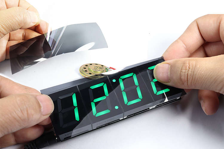
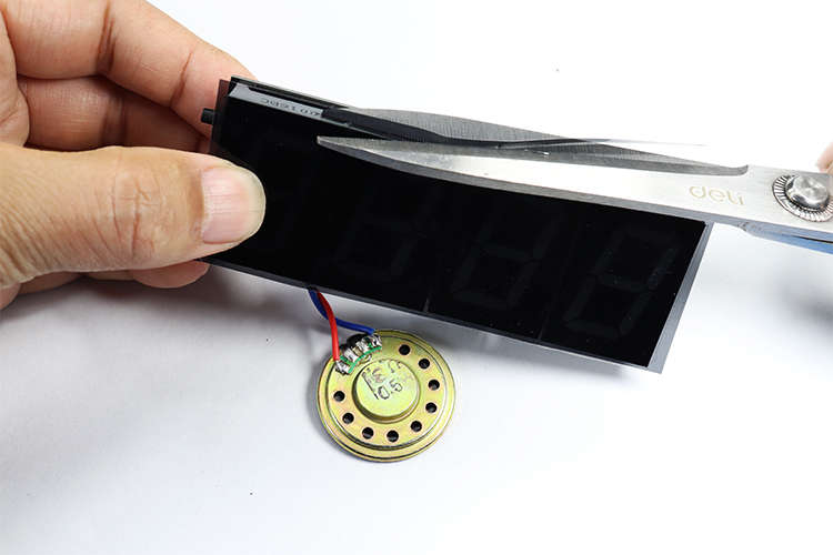
↓用剪刀将滤光膜的边剪整齐。
Use scissors to trim the edge of the filter film neatly.
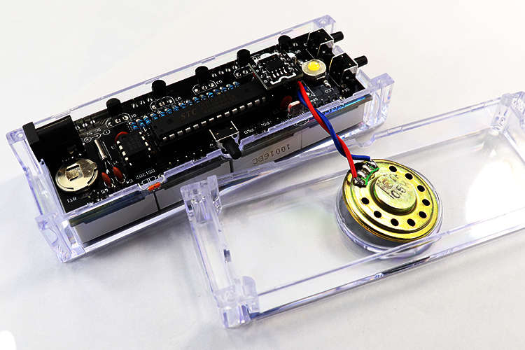
↓将电路板装入外壳,并将光敏电阻和热敏电阻掰入外壳缺口位置。
Put the PCB into the case, and place the photoresistor and thermistor into the notch of the case.
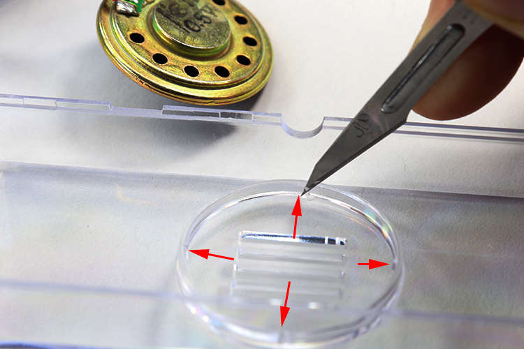
↓安装喇叭时,用小刀将外壳喇叭卡口的4个小点修整一下,刚好卡紧喇叭。
When installing the horn, use a knife to trim the 4 small points of the horn bayonet of the shell to just tighten the horn.
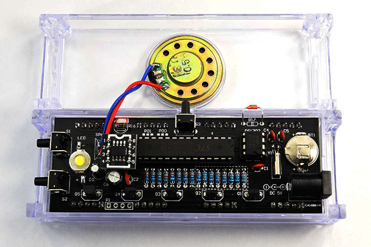
↓将喇叭卡入外壳,可用胶水将喇叭粘紧。
Snap the horn into the case, and glue the horn tightly.
↓将外壳装好,并用螺丝固定好。
Fasten the case and secure it with screws.
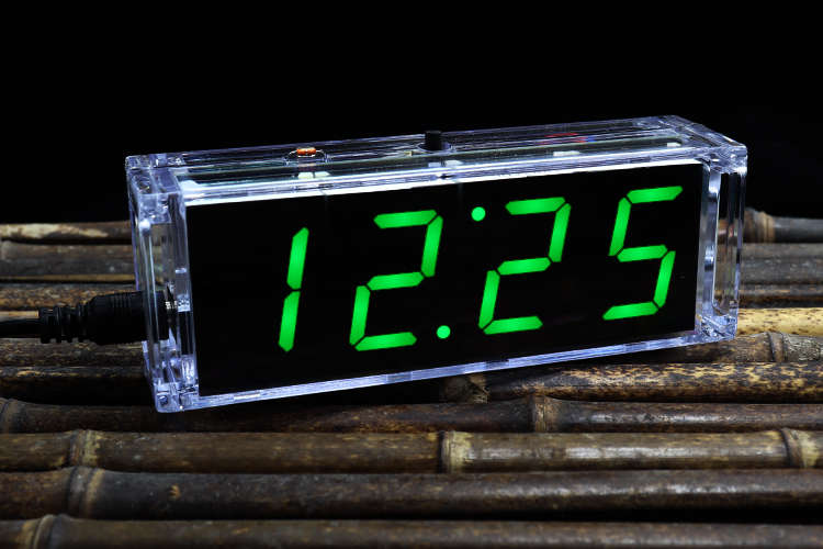
↓安装好的时钟,再按照说明书的方法设置。
The installation is successful, and then set according to the instructions.
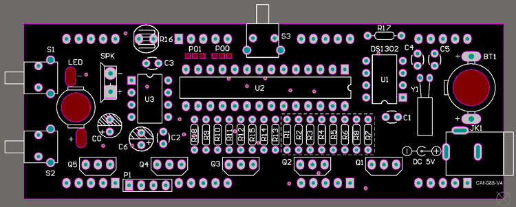
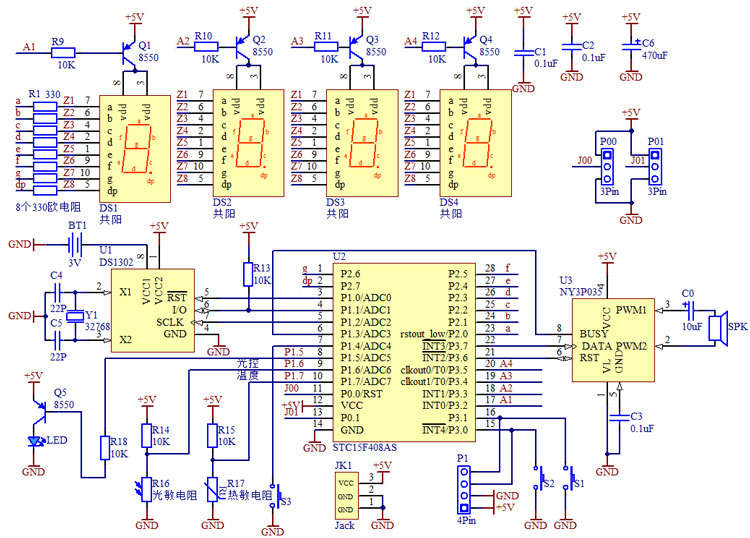
↓电路原理图
Circuit Schematic
------设置说明-------
1、复位:同时按住3个按键5秒,这时显示12:00,复位成功。(默认是关闭了语音和闹钟功能)
2、设置时间、闹钟、整点报
a、调‘时’:按一下功能按键(时数码管闪烁、秒点闪烁),按加键修改‘时’;
b、调‘分’:再按一下功能键(分数码管闪烁、秒点闪烁),按加键修改‘分’(自动从0秒开始);
c、调闹钟‘时’:再按一下功能键(时数码管闪烁,秒点不闪烁),按加键修改闹钟‘时’;
d、调闹钟‘分’:再按一下功能键(分数码管闪烁,秒点不闪烁),按加键修改闹钟‘分’;
e、设定闹钟是否开:再按一下功能键(所有数字显示不动),按加按键,“点4”亮(闹钟开),“点4”灭(闹钟关);
f、设定‘整点报’时间:再按一下功能键(时数码管闪烁),按加键修改闹钟开始时间(例如调到9,就是早上9点开始有整点报);再按一下功能键(分数码管闪烁),按加键修改闹钟结束时间(如调到23,就是早上9点到晚上23点有整点报,夜晚休息时没有整点报,不影响睡眠);
g、设定整点报是否开:再按一下功能键(所有数字显示不动),按加按键,“点3”亮(整点闹开),“点3”灭(整点闹关)
h、按功能键退出,设定完成。
3、温度校正、设置日期、星期
按一下加按键,显示温度;按功能键可以进行温度校正,再按加键确定校正的温度;同时进入年调整,按功能键(年闪烁),按加键调整年(长按会自动加),按功能键确定,再按加键进入日期调整,按功能键(月闪烁),按加键调整月;再按功能键(日闪烁),按加键调整日;按功能键确定。再按加键(显示星期),按功能键(星期闪烁),按加键调整星期,按功能键确定。再按加键退出。
4、模式设定:同时按住“语音”按键和“功能”按键,这时显示一个数字。按功能键可以选择模式1、模式2、模式3。选好需要的模式,断电再通电便可确定模式。
模式1:时间、温度、日期、星期自动循环显示。
模式2:时间、温度自动循环显示。
模式3:只显示时间。
5、光控功能:晚上光线暗时,数码管自动变暗;光线强时数码管变亮。如果将光敏电阻短路,数码管便可以一直亮。
6、数码管贴膜,贴膜自带一层胶,将贴膜撕开,贴在4个数码管上,将多余的边剪掉,贴膜后的显示效果更好一些。
(长按语音按键点亮LED小夜灯,再按一下关闭;短按语音按键,报当前时间)