Click to enter: Setup instructions and schematics
Click to enter: Common troubleshooting
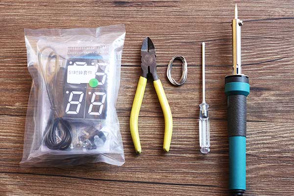
Need the installation tool
Electric soldering iron: choose 30W-40W;
Solder wire: the choice of diameter 0.8-1.2 between the high-quality solder wire, solder wire is not selected, the solder joints have a great impact, bad solder high melting point, the soldering iron is difficult to melt.
Dip pliers: Cut the excess pins of the installed components.
Screwdriver: install the shell with.
Other tools are: scissors or knife (you can cut off the excess digital tube foil); multimeter (easy to carry out fault detection and component testing); iron frame (easy to place electric iron)
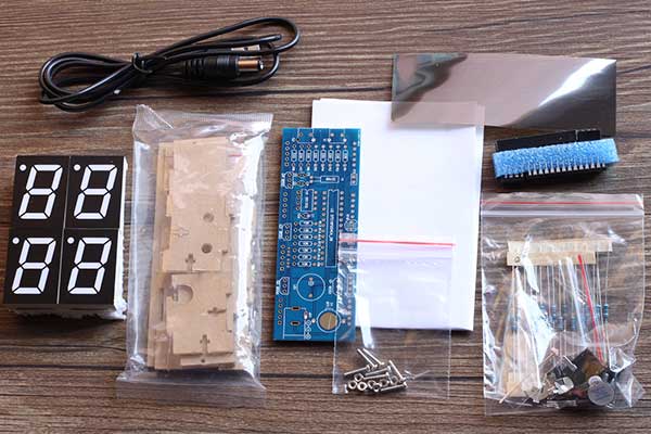
Full set of clock parts, including digital tube, acrylic shell, PCB board, manual, chip and header, component package, USB power supply line, small screws, digital tube foil, brochures, etc.
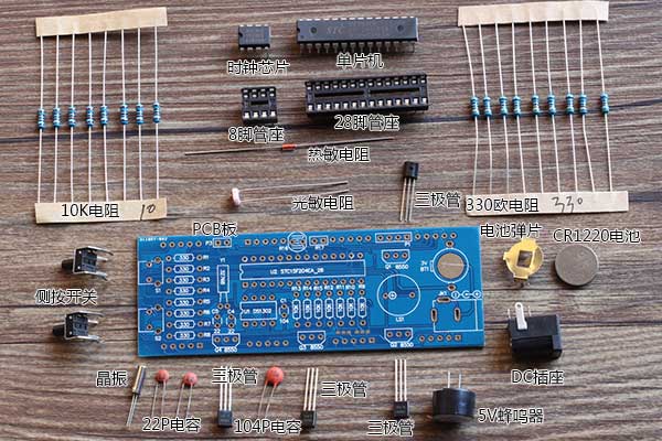
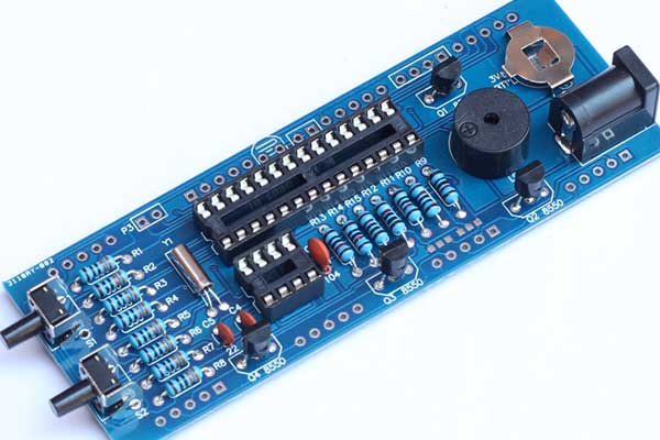
The components are shown as figure.
Resistors, photoresistors, thermistors, crystal, ceramic capacitors are not positive and negative points, you can easily the direction of welding.
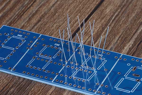
Here we start to welding. The principle is to install from the short to high, install part of the welding part of the inspection, and then install the next part.
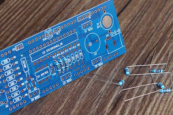
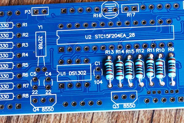
Install the seven resistors, the resistance is 10K ohm, the resistance of the color is (brown black black red brown)
Resistance is not positive and negative points, the first break off the resistance, insert the circuit board R13 R14 R15 R12 R11 R10 R9 these locations.
And then the electric boss to reverse this part of the resistance welding. Pay attention to try not to let the pin to a break, so easy to short circuit with the next side of the solder joints.
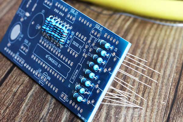
Use the soldering iron to weld this part of the component, pay attention to the solder not too much, because it is double-sided, welding side on the line, do not have both sides are welded.
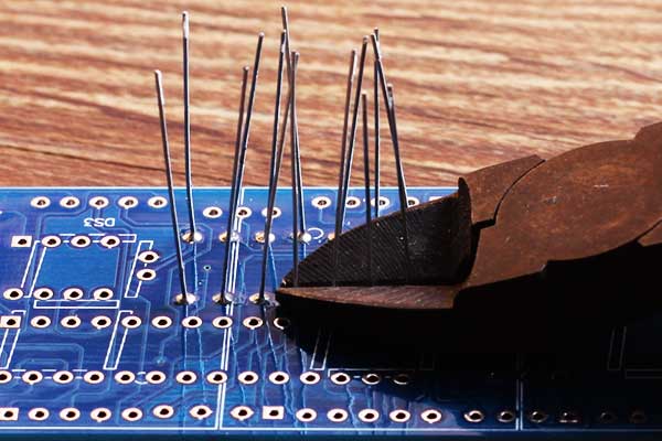
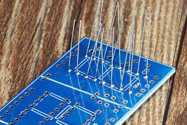
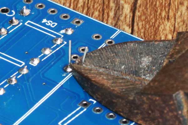
Cut the excess pin with a diagonal pliers
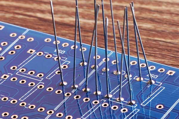
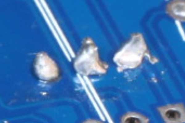
Component pins as short as possible, so it is not easy to encounter with the next welding lead to short circuit. The following figure is the component pin is too long.
Component pins are cut too long for easy short circuits, as shown above
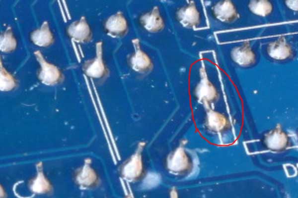
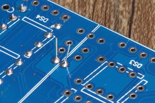
On the map: because the solder melting point is too high, or the electric soldering iron temperature is too low (usually too much oxide on the tip of the lead to low temperature), resulting in poor solder joints, such solder joints most likely to fail.
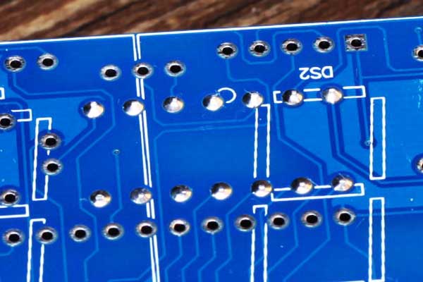
The figure above is a row of resistors installed, there may be more than one resistor in the kit.
R9 R10 R11 R12 These resistors are not welded and will cause 4 digital tubes to turn off
R15 is not welded, will cause the temperature does not work
R14 is not welded, will lead to light control does not work
R13 no welding is good, will lead to the clock display garbled
Then install the next row of resistors.
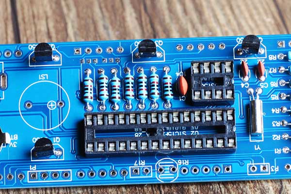
Will be 330 ohm (orange, orange, black, black, brown) resistance all loaded up, (this row of resistance is to control the brightness of the digital tube) if not welded, will lead to digital control.
The soldering iron is used to weld the two rows of components.
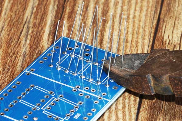
Cut the excess pin with a diagonal pliers
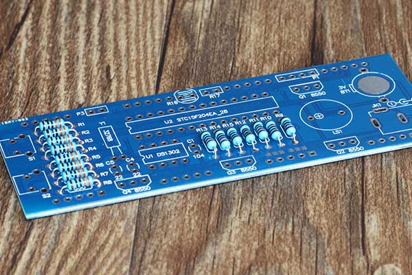
Welding a good two rows of resistors

The above figure is to install the crystal, the crystal is not divided into positive and negative, installed in the Y1 position, the installation pin can not be too short, lying down installation, pay special attention to welding temperature can not be too high, welding time as short as possible.
Special attention to welding temperature can not be too high, welding time as short as possible. The temperature is too high to damage the crystal.
Will crystal off the excess pin cut off
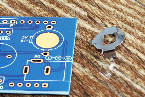
Install the battery pack
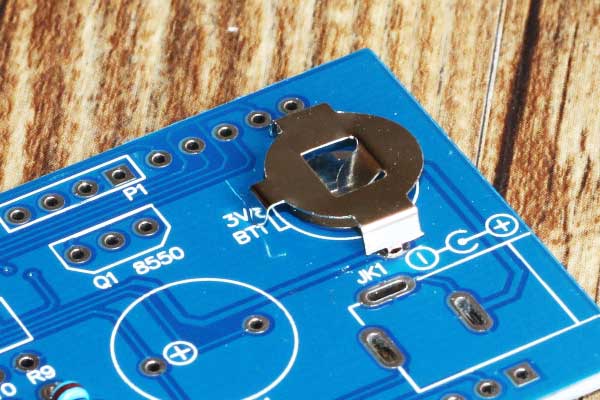
According to the location of the above installation, and welding is good, open out, easy to install the battery.
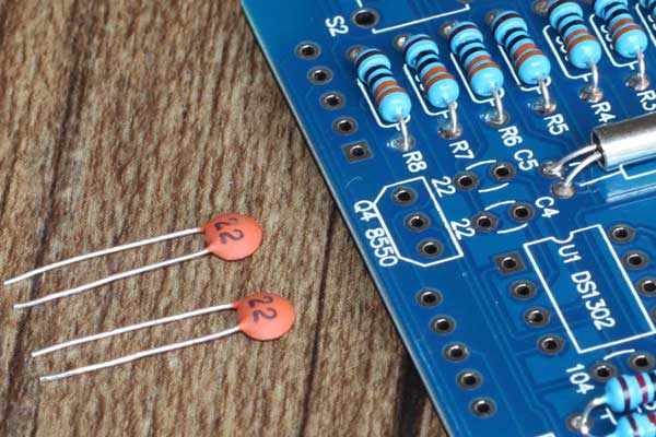
Installation of 22pF ceramic capacitors, ceramic capacitors are not positive and negative, installed in the C4 C5 position. As shown below
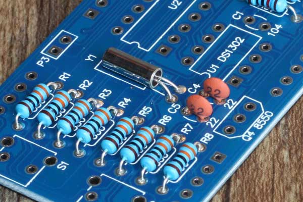
Installed two ceramic capacitors
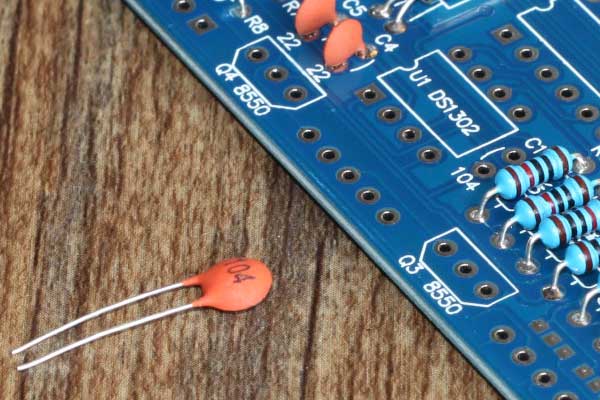
Install 104P ceramic capacitors, there is no positive and negative, installed in the C1 position.
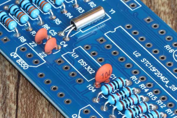
Installed ceramic capacitors.
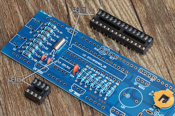
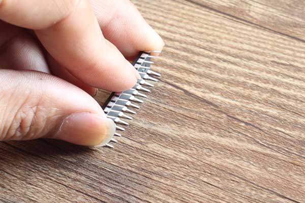
Install the chip header, a total of two tube seats, respectively, 8 feet and 28 feet, there is a gap above, the seat of the gap on the circuit board on the gap mark.
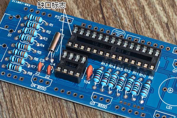
The tube seat installed and welded, the purpose of the socket is to detect the maintenance, direct removal of the chip on the line. If we directly solder the chip on the circuit board, if the wrong welding is not good open.
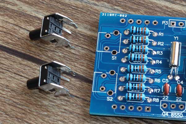
Install side by side switch, as shown above. Switch a total of four feet, in fact, only the middle of the two feet work, you can use a multimeter to measure the middle of the two feet, press the switch when the two feet are connected, release is broken. The edge of the two feet in the circuit is no effect, but from a prescribed role.
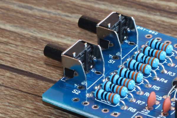
Install the side switch by side
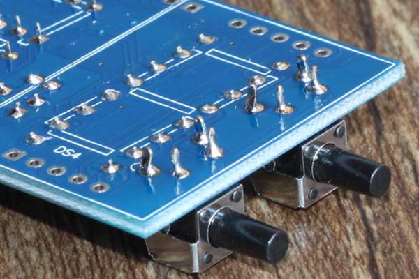
4 feet should be welded, pay attention to welding should be good, can not short circuit, can not Weld.
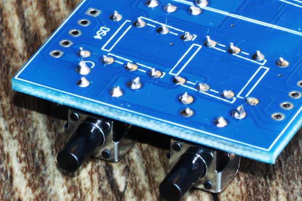
The excess pin cut off, so that will not withstand the digital tube.
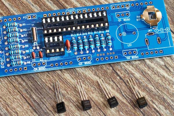
Install the S8550 transistor, the four transistors were controlled 4 digital tube, respectively, installed in the Q1 Q2 Q3 Q4 these locations
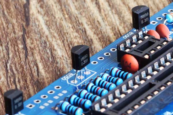
The triode will be installed according to the location of the figure, pin height control in the 5-8mm or so, the semicircle of the transistor at the front of the trapezoidal pattern on the board position, as shown below.
Installed four transistors, pay special attention to the direction of the transistor can not be installed wrong.
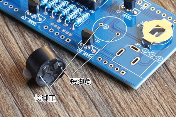
Install the buzzer, the buzzer long feet are positive, short feet are negative, positive pole facing the circuit board marked with the location of the installation, which is 5V active buzzer, directly to the positive and negative pass on the 5V Electric, buzzer will ring.
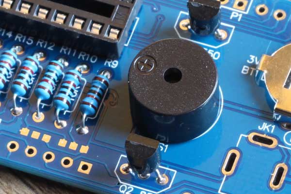
Install the buzzer, you can tear the top of the stickers, easy to speak out.
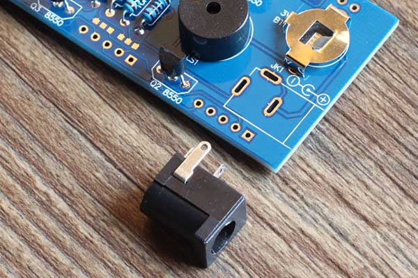
Install the power supply DC socket.
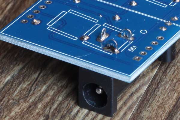
Welding a good DC socket

The extra feet cut off, so that will not withstand the digital tube
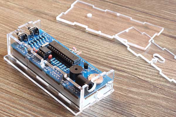
The basic views of the installation is completed, and check the components are not installed wrong,
Check all the solder joints are not welded well,
There is no short circuit, leakage welding, Weld and so on
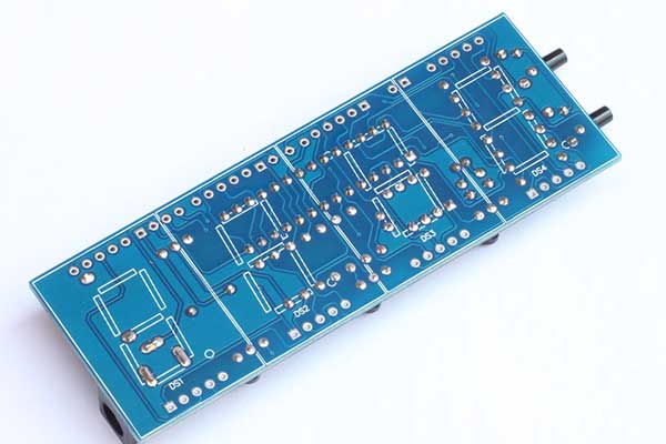
To determine the error without the installation of digital control, the circuit board with a digital tube location and digital control of small signs, the installation of the third digital tube to reverse the installation of digital tube, so just two points together to form a second point.
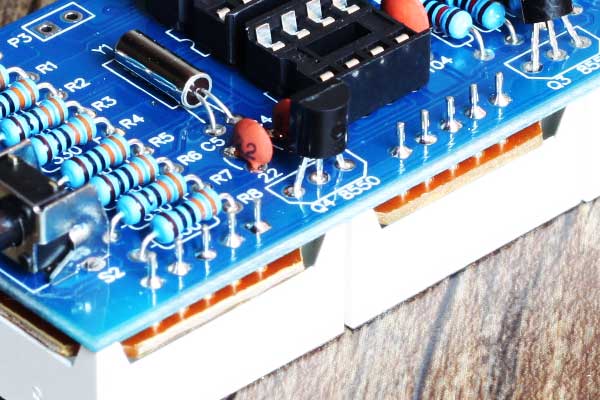
The digital tube of all the pins of the welding, welding a good digital tube pin can not cut feet.
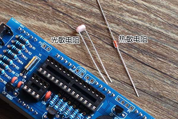
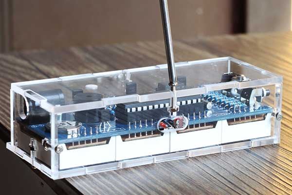
Install the photoresistor and thermistor
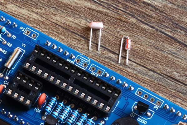
Photoresistor and thermistor, there is no positive and negative points. Cut the extra pins as shown above. And installed in the R16 photoresistor position, R17 thermistor position.
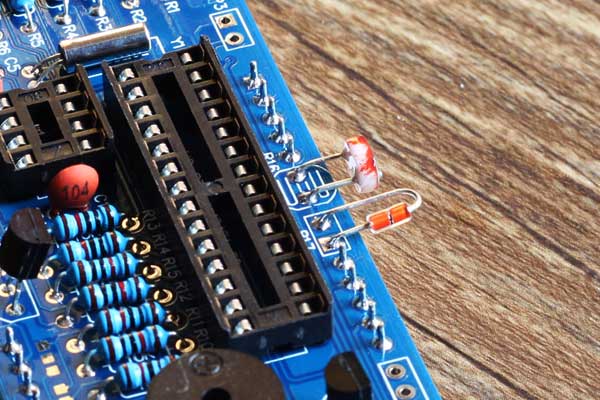
The photosensitive resistor and thermistor welding, pay attention to:, the welding time can not be too long, the temperature can not be too high, or easy to damage the photosensitive resistor.
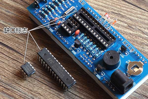
The chip is mounted on a circuit board with a notch aligned with the notch mark on the circuit board.
You can chip on the table to break about, so that some of the pins are so, it is easier to install up.
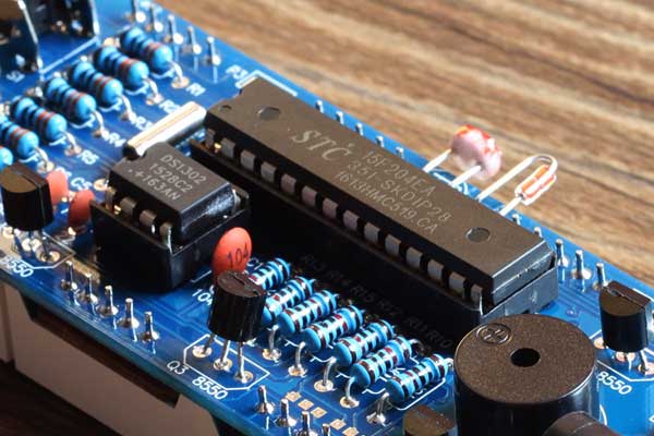
Installed chip. Note that all pins are inserted in place and are in good contact.
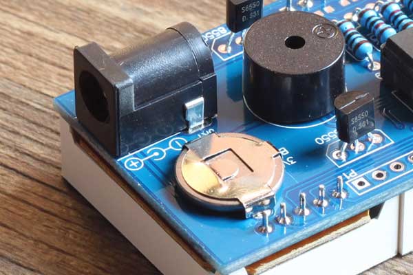
Install the battery with the battery facing up
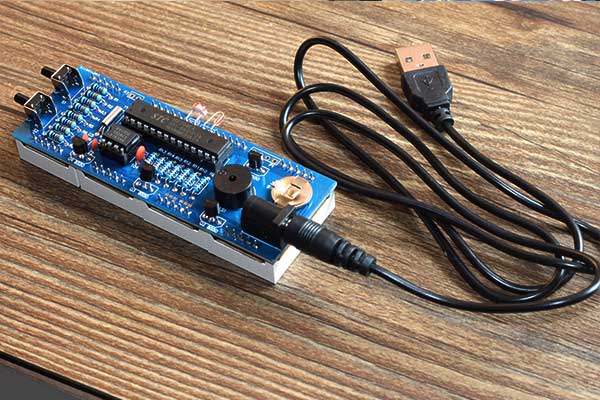
Connected to the USB power supply line, power test. You can use the computer USB port power supply, you can also use the phone charger power supply, as long as the 5V on the line.
With battery power, 1 day there is no electricity. We use a high-capacity battery, it can only work for 3 days, there is no electricity.
接上USB供电线,通电测试。可以用电脑上USB口供电,也可以用手机充电器供电,只要是5V的就行。
用电池供电,1天就没有电了。我们用1节高容量电池,也就只能工作3天,就没有电了。
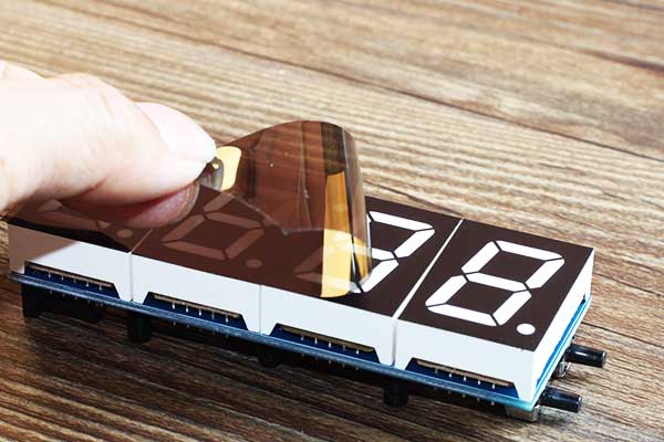
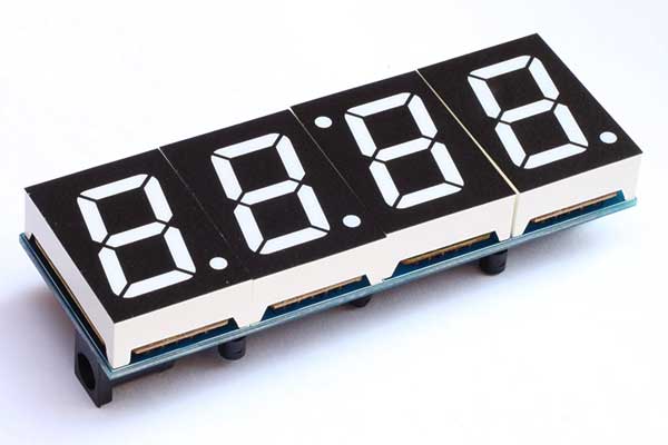
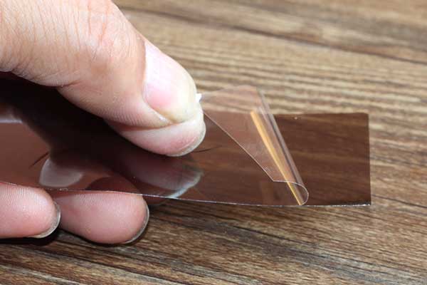
The film directly attached to the digital tube above.
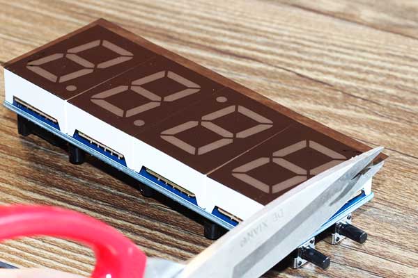
Use a scissors or knife to cut off the extra edges
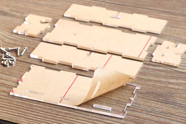
Install the shell. A total of six shell surface, the first two sides of the protective film to tear off.
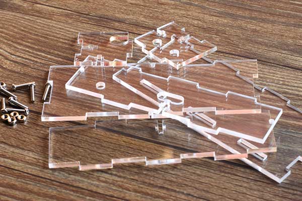
Tear the protective film of the shell.
This film should be torn it, please do not tell you is the wood, not transparent.
6 faces into a box, a total of six screws and six nuts fixed.
Insert the nut into the slot and screw it on.
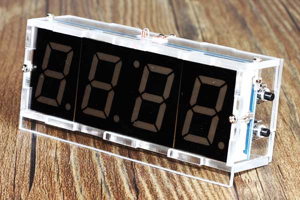
Install the completed map.
Click to enter: Setup instructions and schematics
Click to enter: Common troubleshooting